1. Introduction
1.1 Overview
The GCAN-302 is a CANopen slave and Ethernet converter. The CAN side of the GCAN-302 integrates the CANopen slave protocol. The GCAN-302 converts the CANopen slave protocol signal to the Ethernet signal or converts the Ethernet signal to the CANopen slave protocol signal. With this converter, devices using the CANopen master protocol can connect to Ethernet without changing the hardware architecture and extending the range of CAN bus applications.
Note: CAN-302 is required to be customized.
1.2 Properties at a glance
1.2.1 Hardware
High-speed 32-bit processor
Embedded hardware watchdog timer
Power supply voltage: DC24V, maximum current: 40mA
Electrostatic discharge immunity level: contact discharge±2KV, air discharge ±15KV
Electrical fast transient burst immunity level: ±1KV
Surge immunity level: ±1KV
Operating temperature range: -40℃~+85℃
Operating humidity range: 5%~95% RH no condensation
Dimensions: 113mm * 100mm * 21mm
Standard DIN rail mounting, designed for industrial design
1.2.2 CANopen
Integrated 1 CAN-Bus interface with terminal
CAN-Bus signals include: CAN_H, CAN_L, CAN_GND
CAN-Bus isolation converter insulation voltage: DC1500V
CANopen supports CAN2.0A frame format, supports NMT, PDO, SDO, Heartbeat, Guardlife, SYNC
CANopen baud rates range from 10Kbps to 1Mbps
CANopen node number support 1 ~ 127
1.2.3 Ethernet
RJ45, support 10 / 100M adaptive
Support static or dynamic IP access
Support heartbeat and timeout interrupt function
The working port, the target IP and the target port can be set
After the network is disconnected, the connection resource is automatically restored and the TCP connection is established reliably
Support protocols include EtherNET, ARP, IP, ICMP, UDP, DHCP, DNS, TCP
Compatible with SOCKET work (TCP Server, TCP Client, UDP, etc.), the host computer communication software follows the standard SOCKET rules
2. Installation
2.1 Installation and fixation
GCAN-302 can be installed on a DIN rail, as shown in figure 2.1.
Only CAN_H and CAN_H connect with each other, then CAN_L and CAN_L connect with each other. Then we establish a connection.

Figure 2.1 GCAN-302 module installation
Note: DIN rails require to connect with ground wire.
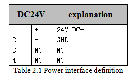
GCAN-302 power interface definitions are shown in table 2.1.

2.2 Connect to PC
Connect the converter to computer with a network cable. Then GCAN-302 LAN interface can establish communication.
2.3 Connect to CANopen
The pin definitions for the CAN side of GCAN-302 are shown in table 2.3.

Only CAN_H and CAN_H connect with each other, then CAN_L and CAN_L connect with each other. Then we establish a connection.
