There are many CAN analyzer users who have devices with different baud rates in their hands, such as 500k car ECU and 125k car radar taken out from the car. They cannot communicate directly, which is very inconvenient in the actual application process. Using the CANbus relay function of USBCAN II pro can solve this problem easily for you.
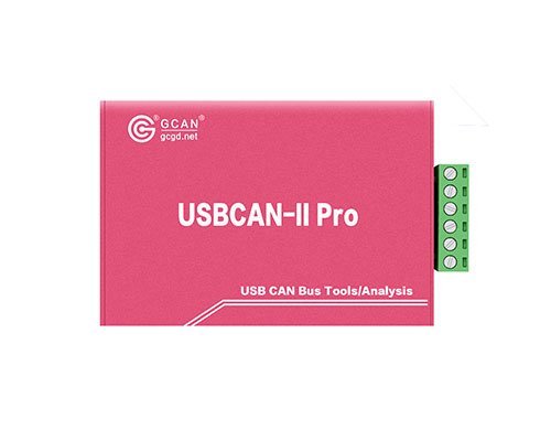
Figure 1 The USBCAN-II Pro analyzer
The USBCAN-II Pro analyzer has two independent CAN bus channels, so it can realize CANbus relay by connecting two CAN bus devices with different baud rates to complete the data exchange between the two devices. In the CANbus relay process of the USBCAN II pro device, you can also connect it to the computer through the USB interface, and use the software to see the data flow between the two devices. This function is very suitable for protocol cracking and we will talk about it in the next news.
Let GCAN show you how to realize the CANbus relay function.
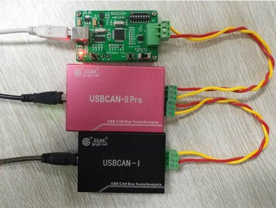
First, wire as Figure 2 below: CAN-H to CAN-H and CAN-L to CAN-L.
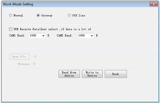
Next, open the ECANTools software, click on the “working mode”, select the normal relay mode, select the baud rate of CAN1 and CAN2 respectively (Note: the baud rate of CAN1 and CAN2 should be the same as the devices connected to CAN1 and CAN2.) If you need to view the data flow between CAN1 and CAN2, check the “USB Receive Data”. After setting, click “Write to Device” , you need to re-plug the device, then you can close the software.
Next, open the ECANTools software, click on the “working mode”, select the normal relay mode, select the baud rate of CAN1 and CAN2 respectively (Note: the baud rate of CAN1 and CAN2 should be the same as the devices connected to CAN1 and CAN2.) If you need to view the data flow between CAN1 and CAN2, check the “USB Receive Data”. After setting, click “Write to Device” , you need to re-plug the device, then you can close the software.


