3 Connection and use
3.1 CAN-Bus configuration
Before using the GCAN-208 converter, users have to configure the parameter of the CAN-Bus.
3.1.1 Configure CAN-Bus baud rate
The baud rate of CAN-Bus range from 5K to 1000K, configured by DIP switch.

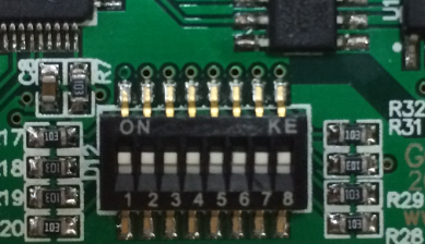
Before power on the converter, open the shell of the converter. The baud rate can be configured by DIP switch. “1、2、3、4” are used to configure CAN1. “5、6、7、8” are used to configure CAN2. Table 3.1 is the example of the baud rate of CAN1.

3.1.2 Configure CAN-Bus termination
Two CAN channels of GCAN-208 converter have already integrated 120Ω termination by DIP switch.
3.2 Connect to Fiber
The two fiber interface of GCAN-208 converter is SC or ST. The fiber transmission mode is single mode or multi mode.
NOTE: When connecting the fiber, the RX should be connected to TX, TX to RX.
3.3 Connect to CAN-Bus
In practical use, users only need to connect the CAN_H to CAN_H and CAN_L to CAN_L, then communication can be realized.
The CAN-Bus network adopts topological structure, only the two furthest terminal need to connect 120Ω terminal resistance between CAN_H and CAN_L. For branch connection, its length should not be more than 3 meters. CAN-Bus nodes connection as shown in figure 3.1.

Note: CAN-Bus using ordinary twisted pair. The relationship between the bus length and baud rate is shown in Table 3.2.

3.4 System LED
The GCAN-208 converter has integrated one POWER indicator, one SYS indicator, one Fiber indicator and two CAN indicators.More functions are shown in table 3.3 and 3.4.

After power on the converter, the POWER and SYS indicator lights indicate that power is being supplied and the system is initializing. Otherwise, it indicates power failure or an error occurred.
After the connection of Fiber Bus and CAN-Bus, when the bus has data transmission, corresponding Fiber and CAN indicators will flash.

