CAN (Controller Area Network) messages are data packets transmitted on the CAN bus and are used for communication between cars and other hardware devices. A typical CAN message consists of multiple parts, and the specific composition may vary depending on different CAN protocol versions and specific applications. The following is an example of a CAN message and its components based on the standard CAN 2.0 protocol:
1. Start of Frame (SOF):
This is a special bit pattern that marks the beginning of a new message. It is usually a dominant bit (in CAN, the dominant bit is usually logic 0 and the recessive bit is logic 1, but this depends on the specific physical layer implementation).
2. Arbitration Field:
(1) Identifier: This is one of the most important parts of the CAN message and is used to distinguish different messages. In the CAN 2.0 standard format, the identifier is 11 bits long; in the extended format, it is 29 bits long (consisting of an 11-bit base ID and an 18-bit extended ID). The identifier determines the priority of the message and how it is recognized by the receiver.
(2) Remote Transmission Request bit (RTR, Remote Transmission Request): This bit indicates whether the message is a data frame or a remote frame. Data frames are used to transmit data, while remote frames are used to request data.
can bus communication protocol
Automobile diagnostic decoding analysis development tool

3. Control Field:
(1) Identifier extension bit (IDE, Identifier Extension): In CAN 2.0B, this bit is used to indicate whether the identifier is in standard format (11 bits) or extended format (29 bits).
(2) Reserved Bit: This bit is reserved for future expansion and is currently not used in most applications.
(3) Data Length Code (DLC, Data Length Code): This 4-bit field indicates the number of bytes in the data field, ranging from 0 to 8 bytes.
4. Data Field: This is the actual data part of the message. The length is determined by DLC and can be up to 8 bytes (64 bits).

5. CRC field (Cyclic Redundancy Check Field): CRC is a check code used to detect message transmission errors. The sending node calculates and appends a CRC to the data, and the receiving node uses the same algorithm to verify the integrity of the data.
6. ACK Field:
(1) Response gap (ACK Slot): This is a bit time used by the receiving node to send a response signal.
(2) Response delimiter (ACK Delimiter): This is a recessive bit after the response field, used to separate the response field and the subsequent end of the frame.
7. End of Frame (EOF): This is one or more recessive bits, marking the end of the message.
A specific CAN message example (expressed in hexadecimal) may be like this:
Frame start: no specific value, detected by hardware
Arbitration field: 123 (assumed an 11-bit identifier, here just for example, actual value depends on the application)
Control field: 80 (assuming extended format, data length is 8 bytes)
Data field: 01 02 03 04 05 06 07 08 (8 bytes of data)
CRC field: CRC value (this value is calculated based on the previous data)
Response field: no specific value, processed by hardware
End of frame: no specific value, detected by hardware
Please note that the above message example does not exactly follow the actual CAN protocol specification, since CAN messages are usually transmitted in binary form, not hexadecimal. In addition, actual CAN messages also need to consider factors such as bit stuffing and bit timing. This example is just to illustrate the basic components of CAN messages.
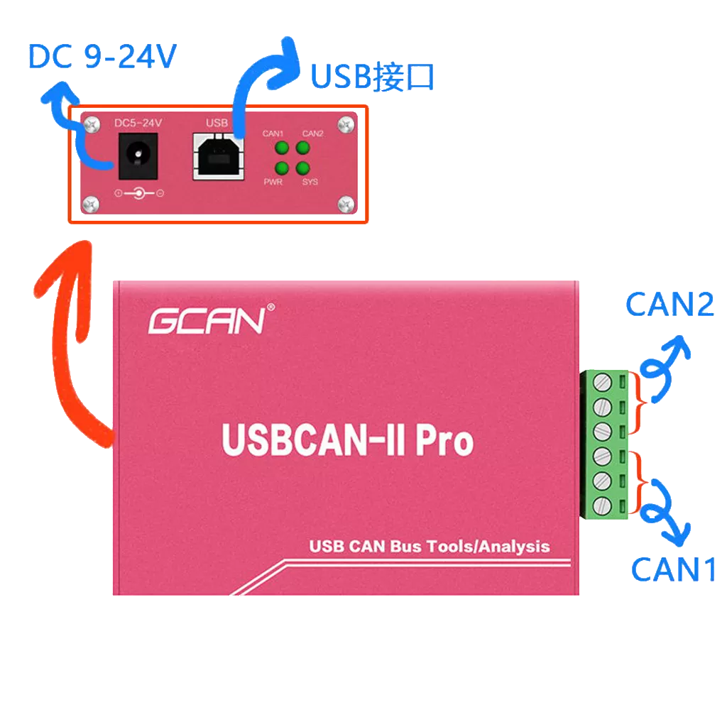
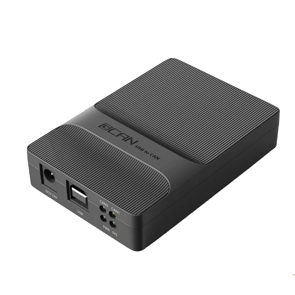
If you need an analyzer that can detect CAN data communication status, you can contact us at any time.
