Do you need a powerful and low cost CAN bus data logger? GCAN is the right place for you!

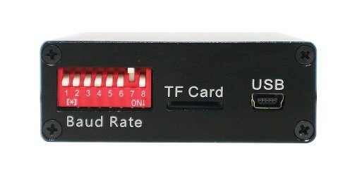
The GCAN-401 CAN bus data logger can be connected to the CAN bus directly after setting the right baud rate. It can support a wide baud rate range from 10k to 1000k. The system clock inside could be configured time as you need. It has high speed 32-bit industrial-grade processor and could extended 32G internal memory(approximately 1.000.000.000 messages).
Data will be stored on TF-card with 2 formats: text file (TXT), binary files (DAT), which you can select by swich up/down the NO.7 code switch. When you want to transfer the logged data to a PC, a standard mini-USB cable can connect them easily.

SYS OFF: System error
SYS ON: System initialization failed
SYS Blinkng: System initialization finifhed
CAN ON then turn OFF: No CAN-Bus data transfering
CAN ON: TF card error
CAN Blinking: CAN-Bus data transfering

GCAN-401 CAN bus data logger has two indicator: SYS indicator, CAN indicator.
SYS OFF: System error
SYS ON: System initialization failed
SYS Blinkng: System initialization finifhed
CAN ON then turn OFF: No CAN-Bus data transfering
CAN ON: TF card error
CAN Blinking: CAN-Bus data transfering
