2 Installation
2.1 Connect to PC
The converter can be connected directly to a PC using an USB to RS232 cable. If PC have RS232 port, using RS232 directly is also possible.
2.2 Connect to CAN-Bus
In practical use, connecting the CAN_H to CAN_H and CAN_L to CAN_L, then communication can be realized.
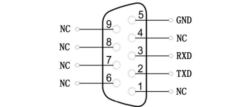
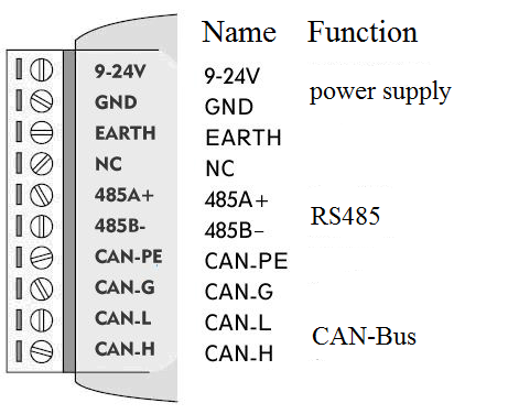
2.3 Interface definition
GCAN-207 converter port definition as shown in figure 2.1 and figure 2.2, using the terminal and the RS232 port, for industrial field application.
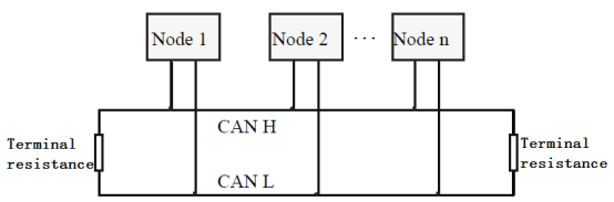
Note: The CAN-Bus network adopts topological structure, only the two furthest terminal need to connect 120Ω terminal resistance between CAN_H and CAN_L. For branch connection, its length should not be more than 3 meters. CAN-Bus nodes connection as shown in figure 2.3.
2.4 System LED
GCAN-207 converter with one PWR indicator, one COM indicator, one CAN indicator to indicate the converter status. More functions are shown in table 2.1.
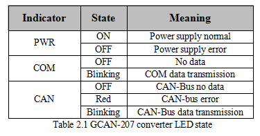
If PWR indicator lights up, it indicates that you plug GCAN-207 converter into an electricity supply, and the system is initialized.
Otherwise, a system power failure or system error has exist. When Serial-bus data is being transmitted, COM indicator will blinking. When CAN-bus data is being transmitted, CAN indicator will blinking in green. If CAN error occurs, CAN indicator will turn red. When COM and CAN indicator blink alternately, it means the converter is in configuration mode.