3. Подключение и использование
3.1 Настройка с помощью соединений с ПК
Конвертер GCAN-302 использует источник питания 24 В постоянного тока. С помощью программы "TCP-CANopen Config" конвертер GCAN-302 может настроить рабочую модель и параметры. GCAN-302 поддерживает только связь между TCP и CANopen, другие протоколы не поддерживаются.
3.1.1 Восстановление заводских настроек
Заводской IP-адрес конвертера GCAN-302: 192.168.1.10. Если пользователь изменил IP и забыл его, он может воспользоваться DIP-переключателем для сброса параметров.
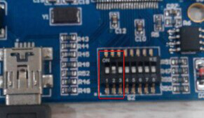
Рисунок 3.1 Коммутатор GCAN-302
Метод работы: сначала откройте корпус конвертера и найдите переключатель, показанный на рисунке 3.1. Переключите переключатель № 2 в положение "ON", затем подайте питание и подождите 3 секунды. После того как индикатор "SYS" замигает, выключите питание и снова установите переключатель в положение "OFF". Теперь конвертер восстановлен до заводского состояния по умолчанию, а заводские настройки системы установлены на IP: 192.168.1.10.
Обратите внимание: после сброса конвертера все настройки параметров и таблицы сопоставления будут очищены. Будьте внимательны.
3.2 Подключение к сети Ethernet
В Ethernet-интерфейс конвертера GCAN-302 встроен чип адаптивного Ethernet 10 / 100M. Конвертер соответствует спецификации стандартного протокола Ethernet.
3.3 Подключение к шине CAN-Bus
Подключение шины CAN-Bus показано на рисунке 3.2.

Рисунок 3.2 Топологическая структура шины CAN-Bus
3.4 Оконечный резистор
Для шины CAN-Bus требуется два оконечных резистора 120 Ом на самой дальней из двух клемм, как показано на рисунке 3.3.

Рисунок 3.3 Подключение GCAN-302 к другому CAN-конвертеру
Обратите внимание: оба конца резистора следует подключить к CAN_L и CAN_H соответственно.
3.5 Системный светодиодный индикатор
Конвертер GCAN-302 имеет один индикатор SYS, один индикатор DAT. Дополнительные функции приведены в таблице 3.2.
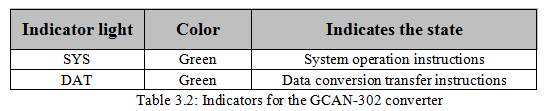
После включения питания конвертера индикатор SYS указывает на то, что питание подается и система инициализируется; в противном случае он указывает на отсутствие питания или возникшую ошибку.
Если по шине идет передача данных, индикатор DAT будет мигать.
