3. используемый конвертер
3.1 Подключение к USB
После установки драйвера и программного обеспечения подключите конвертер к USB-интерфейсу, в диспетчере устройств ПК появится новое устройство USBCAN с именем "GC - Tech USBCAN Device".
3.2 Подключение к CAN
Преобразователь GCAN-206 подключается к шине CAN-Bus в соответствии с главой 2.3, CAN_H к CAN_H, CAN_L к CAN_L.
Сеть шины CAN имеет топологическую структуру, только два самых дальних терминала должны быть подключены к сопротивлению 120Ω между CAN_H и CAN_L. Для соединения ветвей их длина не должна превышать 3 м. Соединение узлов шины CAN показано на рисунке 3.1

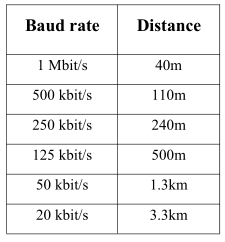
Примечание: в качестве кабеля CAN-шины может использоваться обычная витая пара, экранированная витая пара. Теория максимального расстояния связи зависит от скорости передачи данных по шине, их соотношение показано в таблице 3.1.
3.3 Сопротивление клемм шины CAN-Bus
Для повышения надежности связи и устранения отражений от клемм CAN-шины, две самые дальние клеммы необходимо соединить клеммным сопротивлением между CAN_H и CAN_L, как показано на рисунке 3.2. Значения сопротивления терминала определяются характеристическим сопротивлением кабелей. Например, характеристический импеданс составляет 120Ω.
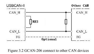
ПРИМЕЧАНИЕ: GCAN-206 не имеет встроенного терминального сопротивления 120 Ом, и заказчику необходимо его добавить.
3.4 Системный светодиодный индикатор
Конвертер GCAN-206 с одним индикатором SYS для отображения состояния конвертера. Один индикатор DAT для индикации передачи данных. Дополнительные функции приведены в таблицах 3.2 и 3.3.

При включении питания конвертера GCAN-206 загорается индикатор SYS, что указывает на наличие питания в конвертере, инициализацию системы. В противном случае имеет место сбой питания системы или системные ошибки. При включении приемопередатчика данных CAN-Bus1 или CAN-Bus2 мигает индикатор DAT.
