3. 연결 및 사용
3.1 PC 연결로 구성하기
GCAN-302 컨버터는 24V DC 전원 공급 장치를 사용합니다. GCAN-302 컨버터는 "TCP-CANopen Config" 소프트웨어를 사용하여 작동 모델과 파라미터를 구성할 수 있습니다. GCAN-302는 TCP와 CANopen 간의 통신만 지원하며, 다른 프로토콜은 지원하지 않습니다.
3.1.1 공장 설정 복원하기
GCAN-302 컨버터 공장 IP: 192.168.1.10. 사용자가 IP를 변경한 후 잊어버린 경우 DIP 스위치를 조작하여 매개변수를 재설정할 수 있습니다.
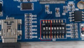
그림 3.1 GCAN-302의 스위치
작동 방법: 먼저 컨버터의 셸을 열고 그림 3.1에 표시된 스위치를 찾습니다. 2번을 "ON"으로 전환한 다음 전원을 공급하고 3초간 기다립니다. "SYS" 표시등이 깜박이면 전원을 끄고 다시 "OFF"로 전환합니다. 이제 컨버터가 공장 출하 시 기본 상태로 복원되었으며, 시스템 공장을 IP: 192.168.1.10으로 설정합니다.
참고: 변환기를 재설정하면 모든 매개변수 설정과 매핑 테이블 설정이 지워집니다. 주의하세요.
3.2 이더넷에 연결
GCAN-302 컨버터의 이더넷 인터페이스는 10/100M 어댑티브 이더넷 칩을 통합합니다. 이 컨버터는 이더넷 표준 프로토콜 사양을 준수합니다.
3.3 CAN-Bus에 연결
CAN-Bus 연결은 그림 3.2에 나와 있습니다.

그림 3.2 CAN-Bus의 토폴로지 구조
3.4 종단 저항
CAN-Bus는 그림 3.3과 같이 두 단자 중 가장 먼 단자에 두 개의 120Ω 종단 저항이 필요합니다.

그림 3.3 GCAN-302와 다른 CAN 컨버터 연결
참고: 저항의 양쪽 끝을 각각 CAN_L과 CAN_H에 연결해야 합니다.
3.5 시스템 LED
GCAN-302 컨버터에는 SYS 표시기 1개, DAT 표시기 1개가 있습니다. 더 많은 기능은 표 3.2에 나와 있습니다.
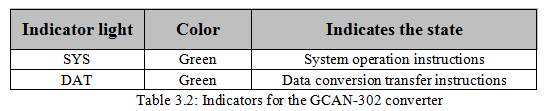
컨버터 전원을 켜면 SYS 표시등은 전원이 공급되고 있고 시스템이 초기화 중임을 나타내며, 그렇지 않으면 정전 또는 오류가 발생했음을 나타냅니다.
버스에 데이터 전송이 있는 경우 DAT 표시등이 깜박입니다.
