3. Conexión y uso
El principio de funcionamiento del GCAN-205 se muestra en la figura 3.1.

3.1 Configuración con conexiones de PC
El convertidor GCAN-205 utiliza una fuente de alimentación de 24 V CC. Mediante el software "GCAN205-ModbusTcp-CAN-configV3.CH", el convertidor GCAN-205 puede configurar el modelo de trabajo y el parámetro. GCAN-205 sólo soporta la comunicación entre Modbus / TCP-CAN, otros protocolos no son compatibles.
3.1.1 Restablecer la configuración de fábrica
IP de fábrica del convertidor GCAN-205: 192.168.1.10. Si los usuarios han cambiado la IP, los usuarios pueden operar el interruptor DIP para restablecer los parámetros

Método de funcionamiento: en primer lugar, abra la carcasa del convertidor para encontrar el interruptor que se muestra en la figura 3.2. En segundo lugar, coloque el nº 2 en "ON" y, a continuación, suministre corriente y espere 3 segundos. Después de que el indicador "SYS" parpadee, desconecte la alimentación y vuelva a poner el interruptor en "OFF". Ahora,
el convertidor se ha restaurado al estado predeterminado de fábrica, la IP de fábrica del sistema:
192.168.1.10.
Nota: después de reiniciar el convertidor, se borrarán todos los ajustes de los parámetros y de la tabla de asignación. Tenga cuidado.
3.1.2 Cambiar la dirección IP del PC
La IP del PC y la IP del GCAN-205 deben estar en el mismo segmento de red.
Por ejemplo: IP del conversor: 192.168.1.10, IP del PC: 192.168.1.1.
Nota: La IP del PC no puede ser la misma que la del conversor.
3.2 Conectar a Ethernet
La interfaz ethernet del convertidor GCAN-205 integra un chip ethernet adaptativo 10 / 100M. El convertidor cumple la especificación del protocolo estándar Ethernet.
3.3 Conexión al bus CAN
En el uso práctico, los usuarios sólo tienen que conectar el CAN_H a CAN_H y CAN_L a CAN_L, a continuación, la comunicación se puede realizar.
La red CAN-Bus adopta una estructura topológica, sólo los dos terminales más alejados necesitan conectar una resistencia de terminal de 120Ω entre CAN_H y CAN_L. Para la conexión de la rama, su longitud no debe ser superior a 3 metros. La conexión de los nodos CAN-Bus se muestra en la figura 3.3.

Nota: El bus CAN utiliza un par trenzado ordinario. La relación entre la longitud del bus y la velocidad en baudios se muestra en la Tabla 3.1.

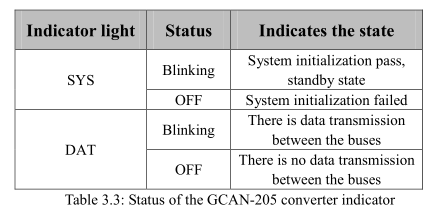
3.4 LED del sistema
Convertidor GCAN-205 con un indicador SYS, un indicador DAT. En la tabla 3.2 se muestran más funciones.

Tras encender el convertidor, el indicador luminoso SYS indica que se está suministrando alimentación y que el sistema se está inicializando; de lo contrario, indica un fallo de alimentación o que se ha producido un error.
Si el bus tiene transmisión de datos, el indicador DAT parpadeará.