2 Instalación
2.1 Conectar al PC
El conversor puede conectarse directamente a un PC mediante un cable USB a RS232. Si el PC dispone de puerto RS232, también es posible utilizarlo directamente.
2.2 Conexión al bus CAN
En el uso práctico, conectando CAN_H a CAN_H y CAN_L a CAN_L, se puede realizar la comunicación.
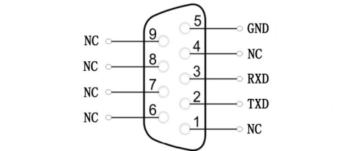
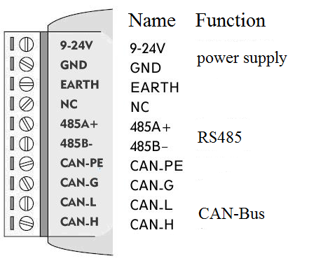
2.3 Definición de la interfaz
Definición del puerto del convertidor GCAN-207 como se muestra en la figura 2.1 y figura 2.2, utilizando el terminal y el puerto RS232, para aplicación industrial de campo.
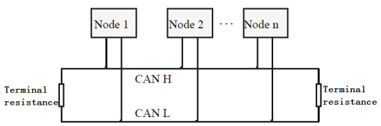
Nota: La red CAN-Bus adopta una estructura topológica, sólo los dos terminales más alejados necesitan conectar una resistencia de terminal de 120Ω entre CAN_H y CAN_L. Para la conexión de ramales, su longitud no debe ser superior a 3 metros. La conexión de los nodos CAN-Bus se muestra en la figura 2.3.
2.4 LED del sistema
Convertidor GCAN-207 con un indicador PWR, un indicador COM, un indicador CAN para indicar el estado del convertidor. En la tabla 2.1 se muestran más funciones.
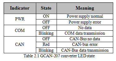
Si el indicador PWR se ilumina, indica que ha conectado el convertidor GCAN-207 a una toma de corriente y el sistema se ha inicializado.
De lo contrario, se ha producido un fallo de alimentación o un error del sistema. Cuando se transmiten datos de bus serie, el indicador COM parpadea. Cuando se transmiten datos del bus CAN, el indicador CAN parpadea en verde. Si se produce un error CAN, el indicador CAN se volverá rojo. Cuando los indicadores COM y CAN parpadean alternativamente, significa que el convertidor está en modo de configuración.