3 연결 및 사용
3.1 CAN-Bus 구성
GCAN-208 컨버터를 사용하기 전에 사용자는 CAN-Bus의 파라미터를 구성해야 합니다.
3.1.1 CAN-Bus 전송 속도 구성하기
CAN-Bus의 전송 속도 범위는 5K~1000K이며, DIP 스위치로 설정할 수 있습니다.
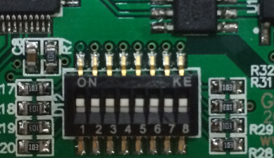
컨버터의 전원을 켜기 전에 컨버터의 셸을 엽니다. 전송 속도는 DIP 스위치로 구성할 수 있습니다. "1、2、3、4"는 CAN1을 구성하는 데 사용됩니다. "5、6、7、8"은 CAN2를 구성하는 데 사용됩니다. 표 3.1은 CAN1의 전송 속도 예시입니다.

3.1.2 CAN-Bus 종단 구성하기
GCAN-208 컨버터의 두 CAN 채널은 이미 DIP 스위치로 120Ω 터미네이션을 통합했습니다.
3.2 광케이블에 연결
GCAN-208 컨버터의 두 파이버 인터페이스는 SC 또는 ST입니다. 파이버 전송 모드는 단일 모드 또는 다중 모드입니다.
참고: 광케이블을 연결할 때는 RX를 TX에, TX를 RX에 연결해야 합니다.
3.3 CAN-Bus에 연결
실제 사용 시에는 CAN_H를 CAN_H에, CAN_L을 CAN_L에 연결하기만 하면 통신을 구현할 수 있습니다.
CAN-Bus 네트워크는 토폴로지 구조를 채택하고 있으며, 가장 먼 두 개의 터미널만 CAN_H와 CAN_L 사이에 120Ω 터미널 저항을 연결하면 됩니다. 분기 연결의 경우, 그 길이는 3미터를 넘지 않아야 합니다. 그림 3.1과 같이 CAN-Bus 노드를 연결합니다.

참고: 일반 트위스트 페어를 사용하는 CAN-Bus. 버스 길이와 전송 속도 간의 관계는 표 3.2에 나와 있습니다.

3.4 시스템 LED
GCAN-208 컨버터에는 전원 표시기 1개, SYS 표시기 1개, 광케이블 표시기 1개, CAN 표시기 2개가 통합되어 있으며, 자세한 기능은 표 3.3 및 3.4에 나와 있습니다.

컨버터 전원을 켜면 POWER 및 SYS 표시등이 전원이 공급되고 있으며 시스템이 초기화 중임을 나타냅니다. 그렇지 않으면 정전 또는 오류가 발생했음을 나타냅니다.
파이버 버스와 CAN-Bus를 연결한 후 버스에 데이터 전송이 있으면 해당 파이버 및 CAN 표시등이 깜박입니다.
