3. 사용 중인 변환기
3.1 USB에 연결
드라이버와 소프트웨어가 설치되면 컨버터를 USB 인터페이스에 연결하면 PC 장치 관리자에서 "GC - Tech USBCAN 장치"라는 새 USBCAN 장치를 찾을 수 있습니다.
3.2 CAN에 연결
GCAN-206 컨버터는 2.3장, CAN_H에서 CAN_H로, CAN_L에서 CAN_L로 CAN-Bus에 연결합니다.
CAN 버스 네트워크는 토폴로지 구조를 채택하고 있으며, 가장 먼 두 단자만 CAN_H와 CAN_L 사이에 120Ω 단자 저항을 연결하면 됩니다. 분기 연결의 경우, 그 길이는 3m를 넘지 않아야 합니다. 그림 3.1과 같이 CAN 버스 노드를 연결합니다.

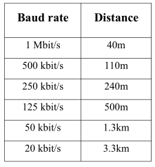
참고: CAN-버스 케이블은 일반 트위스트 페어 케이블, 차폐 트위스트 페어 케이블을 사용할 수 있습니다. 최대 통신 거리의 이론은 버스 전송 속도에 따라 달라지며, 표 3.1에 나와 있는 것처럼 이들의 관계는 다음과 같습니다.
3.3 CAN-Bus 단자 저항
통신 안정성을 향상시키고 CAN 버스 터미널 반사를 제거하기 위해 가장 먼 두 터미널은 그림 3.2와 같이 CAN_H와 CAN_L 사이에 터미널 저항을 연결해야 합니다. 단자 저항 값은 케이블의 특성 임피던스에 의해 결정됩니다. 예를 들어, 특성 임피던스는 120Ω입니다.
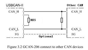
참고: GCAN-206에는 120Ω 단자 저항이 통합되어 있지 않으므로 고객이 추가해야 합니다.
3.4 시스템 LED
컨버터 상태를 나타내는 SYS 표시기 1개가 있는 GCAN-206 컨버터. 데이터 전송을 나타내는 DAT 표시기 1개. 더 많은 기능은 표 3.2 및 3.3에 나와 있습니다.

GCAN-206 컨버터 전원이 켜지고 SYS 표시등이 켜지면 컨버터에 전원이 공급되고 시스템이 초기화되었음을 나타냅니다. 그렇지 않으면 시스템 정전 또는 시스템 오류가 발생한 것입니다. CAN-Bus1 또는 CAN-Bus2 데이터 트랜시버의 경우 DAT가 깜박입니다.
