3 Adaptateur en cours d'utilisation
3.1 Connexion à l'USB
L'adaptateur USBCAN-OBD peut être compatible avec la spécification du protocole USB2.0 à pleine vitesse, compatible avec USB1.1 et USB3.0.
Lorsque le pilote et le logiciel ont été installés, connectez l'adaptateur à l'interface USB, un nouveau périphérique USBCAN nommé "GC - Tech USBCAN Device" peut être trouvé dans le gestionnaire de périphériques du PC. S'il n'y a pas de " !" ou de " ?", cela signifie que le périphérique fonctionne correctement.
3.2 Connexion au réseau CAN
L'adaptateur USBCAN-OBD se connecte au CAN-Bus comme au chapitre 2.3, CAN_H à CAN_H, CAN_L à CAN_L.
Le réseau de bus CAN adopte une structure topologique, seuls les deux terminaux les plus éloignés doivent être connectés à une résistance de 120Ω entre CAN_H et CAN_L. La longueur des branchements ne doit pas dépasser 3 m. Connexion des nœuds du bus CAN
illustré à la figure 3.1 Remarque : le câble du bus CAN peut utiliser un câble à paires torsadées, un câble à paires torsadées blindées. La théorie de la distance maximale de communication dépend du débit en bauds du bus, leur relation étant indiquée dans le tableau 3.1.
3.3 Résistance des bornes CAN-Bus
Afin d'améliorer la fiabilité de la communication et d'éliminer la réflexion des bornes du bus CAN, les deux bornes les plus éloignées doivent connecter une résistance terminale entre CAN_H et CAN_L, comme le montre la figure 3.2. Les valeurs de la résistance terminale sont déterminées par l'impédance caractéristique des câbles. Par exemple, l'impédance caractéristique est de 120Ω.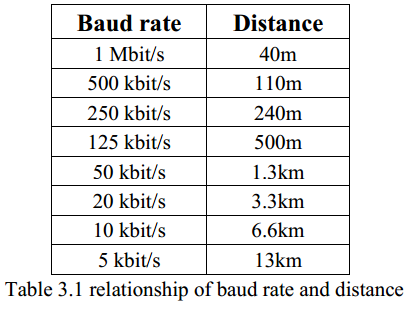 Note : L'adaptateur USBCAN-OBD a intégré une résistance terminale de 120Ω, les utilisateurs peuvent choisir de l'activer ou non.
3.4 LED du système
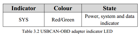
Adaptateur USBCAN-OBD avec un indicateur PWR bicolore pour indiquer l'état de l'adaptateur. D'autres fonctions sont présentées dans les tableaux 3.2 et 3.3.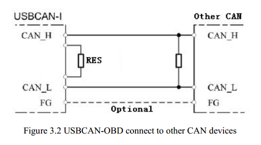 Lorsque l'adaptateur USBCAN-OBD est mis sous tension, le voyant s'allume, ce qui indique que l'adaptateur est alimenté et que le système est initialisé ; dans le cas contraire, une panne de courant ou des erreurs système se sont produites.
 Lorsque l'émetteur-récepteur de données CAN-Bus est activé, l'indicateur clignote.
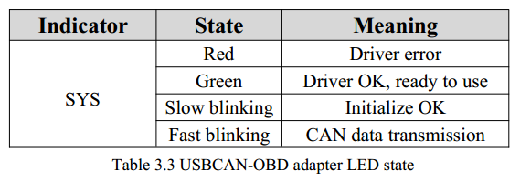
info@gcanbus.com 0086-13644001762 Room 401, D11 Block, SISP, Hunnan District, Shenyang City, Liaoning Province, China Shenyang Vhandy Technology Co, Ltd.