4. Instructions de configuration
4.1 Configuration à préparer
Ouvrez le boîtier du convertisseur, trouvez le commutateur DIP illustré ci-dessous, mettez le commutateur 2 sur "ON", puis connectez-le à l'alimentation, vous pouvez entrer dans le mode de configuration.
Remarque : le GCAN-204 utilise l'interface RS485 pour la configuration, ne pas connecter l'interface "Mini USB".

4.2 Connecter le logiciel
Lorsque le GCAN-204 entre en mode configuration, utiliser une ligne RS485 pour se connecter au PC. Ouvrez le logiciel "ModbusRTU CAN Config", puis configurez les paramètres. L'interface du logiciel est illustrée à la figure 4.1.

Sélectionnez le numéro de série et cliquez sur "Connect". Après avoir établi la connexion, cliquez sur "读参数 Upload" pour lire les paramètres de configuration actuels, comme le montre la figure 4. 2.
Remarque : à ce stade, le convertisseur a été connecté à l'ordinateur, ne cliquez pas plusieurs fois sur "Connecter".

4.3 Configuration des paramètres
Cliquez sur "Communication Set".
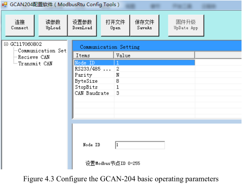
Dans cette interface, vous pouvez définir
ID du nœud : ID du nœud Modbus
Parité : Parité impaire ou parité paire
Taille de l'octet : La longueur des données
Stop Bits : Arrêter le nombre de bits
RS232 / 485 Baud : Vitesse de transmission Modbus RTU
Vitesse de transmission CAN : Vitesse de transmission du bus CAN
Réglage d'usine : Le débit en bauds du côté Modbus RTU est de 57600bps, le débit en bauds du côté CAN est de 250Kbps.
4.4 Configuration de la table de correspondance
Appuyer sur "Add" pour ajouter des données. Adresse Modbus "Receive CAN" : 0x00-0x7F, adresse Modbus de l'émission CAN : 0x100-0x17F.
4.4.1 Réception de CAN
Cliquez sur "Receive CAN", comme le montre la figure 4.4.
COB-ID : définit l'ID de trame du bus CAN
Format d'image : Définit le format de l'image (standard/étendu).
Frame Type (Type de trame) : Définit le type de trame (Données / RTR)
Adresse Modbus : Réglage de la première adresse du registre Modbus
Longueur : Longueur des données de la trame CAN, valeur maximale de 8
4.4.2 Transmettre CAN
Cliquez sur "Transmit CAN" pour ajouter un groupe de mappage de données, comme indiqué sur la figure 4. 5.
COB-ID : définit l'ID de la trame à transmettre aux données CAN-Bus.
Format d'image : Définit le format de l'image (standard/étendu).
Frame Type (Type de trame) : Définit le type de trame (Données / RTR)
Adresse Modbus : Définit la première adresse du registre terminal Modbus.
Longueur : Longueur des données de la trame CAN, la valeur maximale est de 8.
Régler "Trace" ou "Timer".
Trace : Lorsqu'un maître Modbus envoie des données d'adresse Modbus avec une instruction 06, si
les données changent, il déclenche la transmission des données CAN correspondantes.
Minuterie : Vous pouvez régler l'intervalle de temps, envoyer des données CAN de façon circulaire. Il règle l'intervalle en
le "Send Timer", et entrez le nombre décimal. L'unité est la milliseconde. Dans le cas d'un
Par exemple, "enter 1000" peut être envoyé à des intervalles de 1000ms.
4.5 Paramètres de téléchargement
Une fois la configuration terminée, cliquez sur "设置参数 Download", pour télécharger les données de configuration dans la "FLASH" du convertisseur. Si les actions de téléchargement échouent, veuillez les télécharger à nouveau.
Remarque : une fois les données téléchargées avec succès, vous devez placer le commutateur DIP n° 2 sur "OFF", puis redémarrer le convertisseur, afin d'activer la nouvelle configuration.

4.6 Sauvegarde des paramètres
Enregistrez la configuration, cliquez sur "保存文件 SaveAs" pour enregistrer les paramètres sur le PC. Le fichier peut alors être utilisé plusieurs fois.